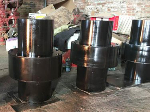
The structure and application range of slider coupling
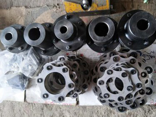
The slider coupling is also known as the metal cross slider coupling. Its slider is in the shape of a ring and is made of steel or alloy. The cross slider coupling is suitable for transmissions with low speed and large transmission torque.The slider coupling is composed of two shaft sleeves and a slider.As a torque-transmitting element, the slider is usually made of engineering plastics. In this case, other materials, such as metal materials, can be selected.
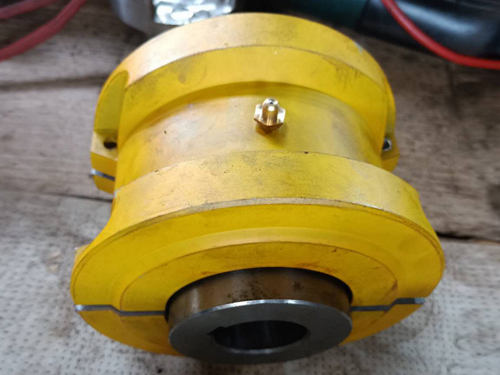
The composition of the slider coupling:
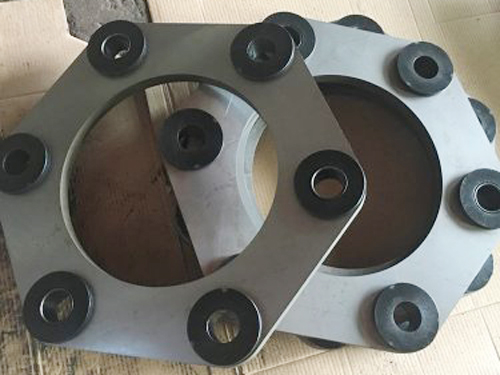
The SL slider coupling is composed of two shaft sleeves and a slider. The slider is usually made of engineering plastic as a torque transmission element. In the case of other materials, such as metal materials, the slider is 90° through both sides. The relatively distributed card slots are connected with the shaft sleeves on both sides to achieve the purpose of transmitting torque. The sliding block and the shaft sleeve are matched with a slight pressure, which can make the coupling have zero during the operation of the equipment. Operation. As the use time increases, the slider may lose its recoilless function due to wear, but the slider is not expensive and easy to replace, and it can still play its original performance after replacement.
Slider couplings are often used in general commonly used motors. In some occasions, they can also be used to connect servo motors. During use, the relative displacement is corrected by the sliding of the slider. Because the half coupling and the intermediate disc form a moving pair, it cannot happen Relative rotation, so the angular velocity of the driving shaft and the driven shaft should be equal. However, when working with relative displacement between the two shafts, the intermediate disk will generate a large centrifugal force, which will increase the dynamic load and wear. Therefore, when choosing It should be noted that the working speed should not be greater than the specified value. This kind of coupling is generally used for speed n<250r/min, the stiffness of the shaft is relatively large, and there is no severe impact.
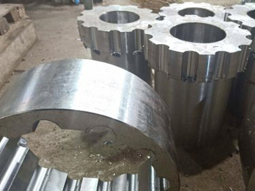
The material of the coupling parts can be 45 steel, thereby increasing the dynamic load and wear.Therefore, when selecting, pay attention that its working speed should not be greater than the specified value.This kind of coupling is generally used at a rotation speed n<250r/min, where the shaft stiffness is relatively large and there is no severe impact.
●The structure of the slider coupling is similar to that of the cross slider coupling. The difference is that the middle cross slider is a square slider. The middle slider is used to slide in the corresponding radial grooves on the end faces of the half couplings on both sides. In order to realize the coupling of the two halves.This coupling has high noise, low efficiency and fast wear. Generally, it is not used as much as possible. It is only used for occasions with very low speed. The slider coupling specified in this standard is suitable for oil pump devices or other occasions with small transmission torque. Relatively compensate the relative offset of the two axes, and the cushioning performance; its working temperature is -20~70°C.The nominal torque transmitted is 16~500N.m.
●Allowable compensation amount: axial △ x=1~2mm, radial △ y ≤ 0.2mm, angular △α≤ 40'.
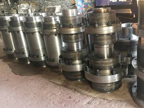
Characteristics of slider coupling:
The material of the sliding block coupling parts can be 45 steel, and the working surface needs to be heat treated to improve its hardness; Q275 steel can also be used when the requirements are lower, without heat treatment.In order to reduce friction and wear, oil should be injected from the oil hole of the middle plate for lubrication during use.Because the half-coupling and the intermediate disc form a moving pair and cannot rotate relative to each other, the angular velocity of the driving shaft and the driven shaft should be equal.However, when working with relative displacement between the two shafts, the middle disk will generate a large centrifugal force, which will increase the dynamic load and wear.Therefore, pay attention to the working speed not greater than the specified value when selecting.This kind of coupling is generally used for speed n<250r/min, the rigidity of the shaft is relatively large, and there is no severe impact.
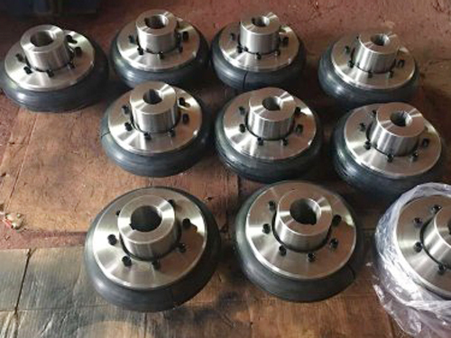
The sliding block and the shaft sleeve are matched with a slight pressure, which can make the coupling have zero operation during the operation of the equipment.As the use time increases, the slider may lose its recoilless function due to wear. However, the slider is not expensive and is easy to replace. After replacement, it can still exert its original performance.Slider couplings are often used in common motors. In some cases, they can also be used to connect servo motors. The sliding of the slider can correct the relative displacement during use.Because it is the friction between the slider and the sleeve that resists the relative displacement, the bearing load between them will not increase due to the increase in the relative displacement.
Advantages of slider coupling:
The sliding block coupling can be used for additional load between the shafts during the automatic control of the motor. The fixed body uses splines to slide, and the inner and outer sleeves inside the sliding body can slide relatively in the axial direction; this coupling can achieve The slip and rotation are integrated; in the case of equal turning diameter, the relatively short size is much smaller than the cross shaft.Improve the uniformity of load distribution on the working surface, and can transmit larger torque, but the elasticity is slightly reduced.
Application of Slider Coupling:
Unlike other couplings, the slider coupling does not have an elastic element that can work like a spring, so the bearing load will not increase due to the increase in the relative displacement between the shafts.In any case, comparing this series of couplings, the ability to choose sliders of different materials is the advantage of this coupling.Juren company can provide a variety of raw material sliders to adapt to different applications according to the specific requirements of customers.Generally speaking, one type of material is suitable for zero, high-torque rigidity and large torque, and the other type of material is suitable for low-precision positioning, without zero, but has the functions of absorbing vibration and reducing noise.The non-metallic slider also has good electrical insulation and can be used as a mechanical fuse.When the engineering plastic slider is damaged, the transmission effect will be terminated, so as to protect the valuable mechanical parts.This design is suitable for large parallel relative displacements.The three-part design of the slider coupling split body, which has the ability to compensate for the axial deviation, for example, cannot be used in push-pull applications.At the same time, because the slider is floating, the two-axis motion slider will not fall off.
Place of origin
Mainly include: Mainland China, Taiwan Province of China, Japan, Western Europe.
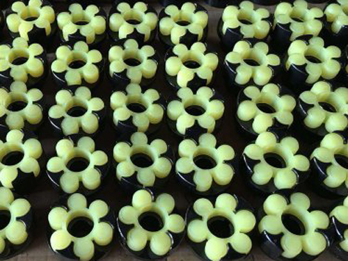
The difference between plum blossom coupling and slider coupling:
The relative displacement of the two shafts of the quincunx elastic coupling is within the rated allowable range of the coupling.Install the two shaft sleeves on the shaft so that the tenon faces are facing each other.Use a wrench to fully tighten the screw on one side of the shaft sleeve to the recommended seating torque. Insert the torx spacer into the fixed shaft sleeve so that its prongs can touch the bottom of the groove of the shaft sleeve.Insert the bushing of arrangement 2 on the quincunx spacer and the protruding claws can touch the bottom of the groove of the bushing.When inserting, it will require relative force to complete. This is normal.The distance between the two shaft sleeves prevents the metal of the two shaft sleeves from contacting directly.Fully tighten the screw to its in-place torque, and the entire shaft at fixed position 2 is sleeved on the shaft.
The relative displacement of the two shafts of the slider coupling is within the rated allowable value of the coupling.Install the two shaft sleeves on the shaft so that the tenon faces are facing each other.Rotate the two shaft sleeves so that the driving tenon with the tenon surface is at a 90° angle, align the groove of the slider with one of the tenons, and insert the slider onto the tenon by hand.Put the axial limit washer into the groove bottom of the slider.Tighten the screws according to the in-place torque, and the entire fixed two shafts are sleeved on the shaft.Take out the gasket and make the two bushings face each other with the slider to balance the relative axial displacement
Next:Nothing