Rigid movable coupling
Types of rigid movable couplings (couplings without elastic components): Oldham couplings, universal couplings and drum gear couplings.
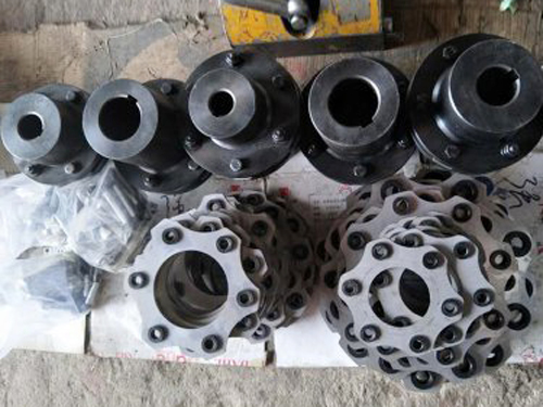
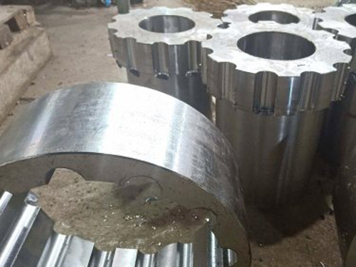
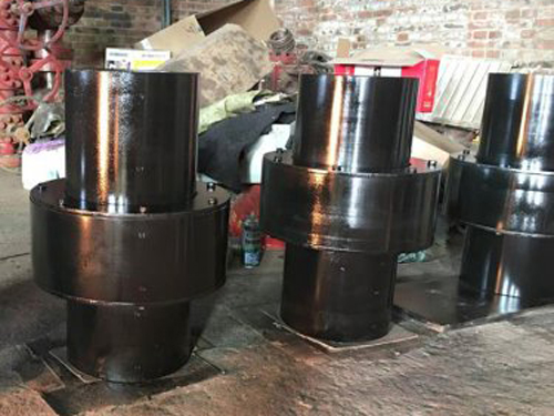
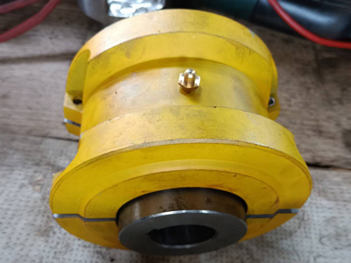
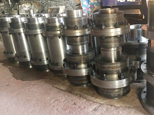
XNUMX. Gear coupling
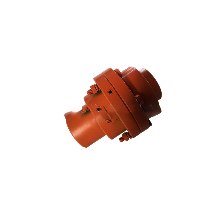
A. Composition: two outer sleeves with inner teeth and flanges, and two inner sleeves with outer teeth;
B. Working principle: The two inner sleeves are respectively connected with two shafts by keys, and the two outer sleeves are connected by bolts, and the torque and movement are transmitted through the meshing of the inner and outer teeth.
C. Features: In order to compensate the relative displacement of the two shafts, the gear teeth of the outer gear ring are made into drum-shaped teeth, and the tooth top is made into a spherical surface with a line on the axis, and the tooth top and the side of the tooth are larger.
Through the top clearance and backlash between the meshing teeth, it has the function of allowing the radial, axial and angular displacement compensation between the two shafts; high speed (up to 3500r/min), can transmit large torque (can be Up to 106N·m), and can compensate for large comprehensive displacements, work very high, and does not require high installation accuracy, so lubrication is required;
D. Disadvantages: high quality, difficult to manufacture, and high cost.
E. Application: Widely used in large and heavy machinery and equipment such as automobiles.
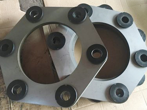
Two, cross slider coupling
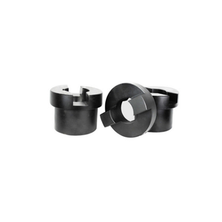
A. Structural features: It is connected by half couplings 1, 3 (left and right sleeves) and floating disk 2 (cross slide block), and the two shafts rotate together; the tenon of the floating disk can be in the half coupling Sliding in the groove; the friction is high and needs to be lubricated.
B. Advantages: small radial size and simple structure
C. Disadvantages: But the impact resistance is poor, the sliding block and the groove are easy to wear and need to be lubricated; the cross block will generate a large centrifugal inertia force due to the radial displacement, which will bring additional load to the shaft and the bearing.
D. Application occasions: often used in occasions with high rigidity, low speed and low impact.
Three, universal coupling
A. Structure: It is composed of a cross shaft, two universal joint forks, and four needle bearings; the rotation (axis) of all rotating pairs intersects at a point O, and the angle between the two shafts is α; A device (coupling) that transmits movement between two intersecting shafts with a variable included angle.
B. Working principle: When shaft Ⅰ rotates once, shaft Ⅱ will also make one revolution, that is, the average transmission ratio of the two shafts is 1; however, the instantaneous transmission ratio of the two shafts is not constant at 1, but is periodic Variable; this characteristic of universal joints is called the unevenness of the instantaneous transmission ratio; as far as a single universal joint is concerned, when there is an angle between the input shaft and the output shaft, the angular velocity of the two shafts is not equal, that is, the universal joint The joint has unequal velocity; the larger the angle α between the two shafts, the more obvious the speed fluctuation of the driven shaft; therefore, α should be between 35° and 45°.In order to prevent the angular velocities of the main and driven shafts from being unequal; for all the shortcomings of the variable speed transmission of the driven shaft in the above universal joints, they are often used in pairs.
C. Advantages: It has a large angular compensation capability, compact structure, and transmission;
D. Disadvantages: additional dynamic load will be generated in the transmission, and the speed should not be too high;
E. Application: It is mainly used in the transmission where two shafts intersect, and the medium and low speed occasions such as heavy load, medium load and light load, such as machine tools and automobiles.
F. Double universal joints should meet the conditions:
In order for the mechanism to obtain a constant transmission ratio, the mechanism must meet the following three conditions: XNUMX. The three axes of the driving shaft, the driven shaft and the intermediate shaft should be located in the same plane.
XNUMX. The angle between the driving shaft, the driven shaft and the intermediate shaft should be equal:
XNUMX. The fork surfaces at both ends of the intermediate shaft should be in the same plane.